Material Testing Blog

HomeMaterial Testing Blog

What Are Quick Connect Couplers and How Do They Work?

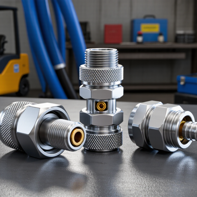
Quick Connect Couplers are small components with a significant job. They connect and disconnect fluid lines without requiring tools, lengthy shutdowns, or spilled hydraulic oil. In a workshop, that can mean changing an attachment beside a loader in seconds. The fitting clicks into place, locks, and creates a sealed passage for hydraulic fluid, air, water, or other compatible media.

Hydraulic engineer and fluid-power educator Steve Skinner describes their purpose this way: “A good coupler saves connection time without sacrificing sealing reliability.” That principle explains why design details matter. A coupler typically uses a male plug, a female socket, locking balls or sleeves, and internal valves. When connected, the valves open and allow flow. When disconnected, they close to limit leakage and contamination.

Not every coupler fits every application. Pressure ratings, temperature limits, thread standards, seal materials, and fluid compatibility must match the system. A coupling that feels secure may still be unsuitable. Small particles can damage seals. Trapped pressure can prevent connection. These practical issues are easy to underestimate.

The best selection process starts with the equipment’s real working conditions. Check flow requirements, operating pressure, connection frequency, and exposure to dust or moisture. Then inspect the coupler regularly for worn seals, damaged locking mechanisms, or difficult engagement. Quick does not mean careless. A reliable connection should feel positive, remain stable under load, and release safely when maintenance begins.

What Are Quick Connect Couplers and How Do They Work?

Quick Connect Couplers Defined: ISO 7241 Types, Parts, and Industrial Roles

Quick connect couplers are detachable fittings that join fluid lines without tools. ISO 7241:2017 classifies common hydraulic couplers into Type A and Type B. Type A uses a ball-locking design, while Type B generally uses a sleeve-based connection. Both support interchangeability within compatible dimensions and pressure limits.

A typical coupler contains a plug, socket, locking balls, sleeve, valve, spring, and sealing rings. Push the plug into the socket. The sleeve moves, locking balls engage, and internal valves open. Disconnecting reverses this action. The valves close before separation, reducing fluid loss and air entry. Small details matter. Damaged seals can create leaks, heat, and unstable actuator movement.

Industrial roles include excavators, agricultural machinery, injection-molding equipment, hydraulic test benches, and pneumatic tooling. The U.S. Department of Energy’s Improving Compressed Air System Performance sourcebook reports that leaks may waste 20% to 30% of compressor output. A poorly seated pneumatic coupler can contribute to that loss. ISO compatibility is helpful, but it does not prove safe performance. Working pressure, temperature, media, flow rate, and contamination still require verification. That is where practice gets less tidy. Field operators may select by thread size alone, yet thread compatibility does not guarantee valve alignment or adequate sealing. Regular inspection remains essential.

What Are Quick Connect Couplers and How Do They Work?

ISO 7241 quick connect couplers are hydraulic connectors designed to join and separate fluid lines efficiently. Type A and Type B couplers use spring-loaded poppet valves, locking mechanisms, sleeves, and seals to help connect hoses while limiting fluid loss and contamination.

The chart shows common ISO 7241 nominal bore sizes in millimetres: 6.3, 10, 12.5, 19, 25, 31.5, 38, and 51. Nominal bore is an identifying size dimension; actual flow rate and working pressure depend on the coupler design, fluid, temperature, pressure drop, and installation.

How Coupler Valves Open and Seal During Connection and Disconnection

What Are Quick Connect Couplers and How Do They Work?

Quick connect couplers join fluid lines without using a wrench. Their real value appears inside the valve. Each half usually contains a spring-loaded poppet, a sealing surface, and an O-ring. Before connection, both poppets remain closed. Springs push them against their seats, blocking fluid and limiting leakage.

During connection, the male half enters the female socket and moves a locking sleeve. Internal noses then press the two poppets together. The valves open almost at the same moment, creating a continuous passage for air, water, or hydraulic fluid. A firm click confirms that the locking balls or sleeve have engaged. The connection should feel secure, not forced.

Disconnection reverses this sequence. Pulling the sleeve releases the locking mechanism, while internal springs drive both poppets back onto their seats. Fluid flow stops on each side, although a small amount may remain trapped between the valves. That detail is often underestimated. Residual pressure can make separation difficult or cause a sharp spray. Operators should depressurize the line when the system allows it and inspect the sealing faces for dirt or scratches. Even a clean-looking coupler can leak after repeated side loading. Valve timing also varies with wear, temperature, and pressure, so “instant shutoff” is a practical goal, not a perfect guarantee.

What Are Quick Connect Couplers and How Do They Work? - How Coupler Valves Open and Seal During Connection and Disconnection

Operating sequence, valve behavior, sealing functions, and typical applications

Operating Stage User Action Locking Mechanism Coupler Valve Flow Path Sealing Condition Functional Result
1. Disconnected The plug and coupler are separate. The sleeve remains in its normal locked position; locking balls or pins retain the coupler body. The internal poppet or valve element is closed. The passage through the coupler is blocked. The valve seat and seal prevent fluid from escaping through the coupler. The circuit is isolated, helping limit fluid loss and air entry.
2. Sleeve Retracted The operator pulls back or rotates the release sleeve. The sleeve moves the locking balls or pins away from the plug-retention groove. The valve remains closed until the plug is fully inserted. No open flow path is created at this stage. The coupler-side valve remains sealed. The coupler is ready to receive the matching plug.
3. Plug Inserted The plug is pushed axially into the coupler. The plug nose passes the locking elements and reaches the internal stop. The plug contacts the coupler poppet or actuator. The flow path is still restricted while the connection is being positioned. The plug seal engages the coupler bore before the valves open. The connection is aligned and prepared for valve opening.
4. Locked and Open The sleeve is released and returns to its locking position. Balls, pins, or locking segments engage the plug groove. The mating valve elements push each other open. A continuous passage is created through the coupled pair. Radial or face seals contain the fluid around the joined interface. Fluid can flow with minimal interruption when the coupling is correctly rated.
5. Flowing Service The connected system operates within its specified limits. The locking mechanism carries axial separation forces and vibration loads. The valve remains open through the pressure and flow range permitted by the design. Fluid passes through the valve seats and internal bore. Static seals remain compressed against their mating surfaces. The coupler provides a detachable connection for hydraulic, pneumatic, fuel, coolant, or process-fluid lines.
6. Disconnection Started The operator stops the system and retracts or rotates the sleeve. The locking elements are released from the plug groove. The valve actuator loses support and begins returning toward the closed position. The passage begins to close before the plug leaves the sealing area. The sealing interface remains engaged during the initial separation movement. The design helps reduce fluid release during normal disconnection.
7. Valves Closed The plug is pulled out of the coupler. The sleeve guides the locking elements over the plug as it exits. Spring force, pressure force, or both return the valve to its seat. The coupler-side passage is blocked; a double-shutoff pair closes both sides. The valve seat and elastomeric or polymeric seals isolate the remaining fluid. The line is separated with limited spillage, subject to pressure, temperature, and fluid compatibility.
8. Fully Disconnected The sleeve is released and the plug is removed completely. The coupler returns to its locked standby position. The coupler valve remains closed until the next compatible connection. The external circuit is interrupted. The closed valve limits contamination and helps retain system fluid. The connection can be stored, capped, or reconnected when required.
Important operating factors: Actual pressure rating, temperature range, flow capacity, connection force, leakage performance, and seal material depend on the coupler design, size, fluid, and applicable technical specification. Always connect and disconnect only under conditions permitted by the equipment documentation.

Flow Paths, Pressure Ratings, and ISO 16028 Face-Seal Performance

Quick connect couplers create a removable hydraulic connection without lengthy assembly. Their internal poppets open when the male and female halves engage, forming a continuous flow path. When disconnected, the poppets close and limit fluid loss. In practice, a clean, straight alignment matters. Small details matter.

ISO 16028 couplers use a flat-face design that reduces exposed cavities. This helps limit air entry, fluid leakage, and contamination around the connection. During coupling, the mating faces press together and form a face seal. The result is a cleaner interface than many older recessed designs. However, face seals are not maintenance-free. Dust, damaged seals, or angled engagement can still cause leakage.

Pressure ratings require careful interpretation. A catalog may list working pressure, proof pressure, and burst pressure separately. Working pressure is the useful operating limit, while proof pressure reflects a controlled test level. Burst pressure indicates failure resistance, not a safe operating target. Flow rate also affects performance because narrow passages create pressure drop and heat. I have seen systems perform well at low flow, then struggle when demand rises. That is an easy detail to miss. Temperature, fluid type, pulse frequency, and trapped pressure must also be checked. ISO 16028 describes dimensional and performance expectations, but the complete assembly still depends on hose routing, seals, and installation quality. No rating survives every condition.

Coupler Selection by Fluid, Port Size, Pressure, Temperature, and Flow Rate

Quick connect couplers simplify hose changes, but selection should begin with the fluid. Hydraulic oil, water, air, and aggressive chemicals require different seal materials and body designs. A coupler suitable for air may swell, leak, or fail when exposed to oil. The U.S. Department of Energy reports that compressed-air leaks can waste 20–30% of compressor output. Poor coupler connections can add to this loss. I have learned that compatibility deserves more attention than appearance.

Port size must match the hose and equipment connection. A smaller port can restrict flow, even when its pressure rating looks adequate. Check the required operating pressure, maximum surge pressure, and connection type. Never select only by the catalog’s maximum value. The working margin matters. Temperature is equally important because heat can reduce seal life and change fluid viscosity. ISO 7241 and ISO 14541 provide useful dimensional and performance references for hydraulic quick couplings, but field conditions still require verification.

Flow rate is often misunderstood. A coupler’s internal valve creates pressure drop, especially at high flow. Compare tested flow curves, not just nominal port size. The Hydraulics Institute’s pump-system guidance emphasizes evaluating system resistance across operating conditions. That principle applies here. Measure actual flow, inspect the mating faces, and confirm cleanliness before installation. A dry, dusty workshop can expose a weakness that laboratory ratings do not show. My earlier assumption was simple: bigger is always safer. It is not. Oversizing can increase cost, weight, and trapped fluid without fixing a mismatched connection.

Safety, Leakage Control, and SAE J1502 Testing Requirements

What Are Quick Connect Couplers and How Do They Work?

Quick connect couplers join hydraulic lines without using threaded tools. A spring-loaded sleeve locks the mating halves together. Internal valves then open, allowing pressurized fluid to pass. When disconnected, the valves close and limit fluid loss. This sounds simple. In practice, dirt, pressure, and worn seals can change everything.

Safety depends on controlling trapped energy before connection or removal. Operators should isolate the circuit, release pressure, and inspect both faces. A 2023 U.S. Bureau of Labor Statistics report recorded about 2.6 million nonfatal workplace injuries and illnesses. The figure is not coupler-specific, but it shows why small connection tasks deserve attention. Fluid injection injuries can look minor at first. They are not.

SAE J1502 defines performance testing for hydraulic quick-action couplings, including leakage, pressure resistance, impulse durability, and connection performance. Testing commonly exposes couplers to repeated pressure cycles, temperature changes, and mechanical stress. Leakage should be measured, not judged by appearance. A dry exterior is useful evidence, but not proof. ISO 4413 also emphasizes safe hydraulic-system design and stored-energy control. Field inspections should record seal condition, locking-sleeve movement, and visible wear. One weakness remains: laboratory results may not reflect contaminated worksites. That gap needs honest review.

Go to Top