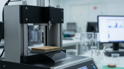
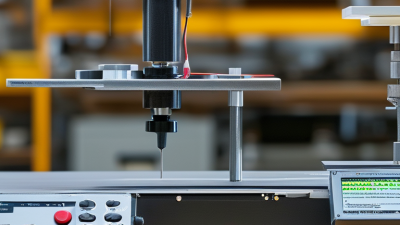
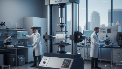
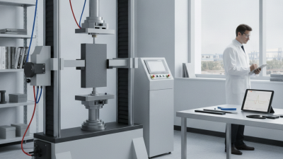
Choosing a peel tester machine in 2026 requires more than comparing prices, touchscreen size, or advertised force ranges. The correct instrument must reproduce your real packaging conditions. That means examining adhesive type, substrate, peel angle, test speed, sample width, and expected failure mode. A laboratory testing flexible pouches may need different fixtures from a manufacturer evaluating labels or medical packaging.
Dr. Bruce Harte, a respected packaging-testing educator, once stated, “A test is useful only when its method matches the question.” That principle remains practical. A reliable peel tester machine should support recognized methods, including ASTM D3330 or ISO 8510, where applicable. It should also provide stable speed control, accurate load measurement, secure sample clamping, and traceable calibration records. Small details matter. A slipping strip can distort the entire result.
In this guide, we examine how to match machine capability with production needs, quality targets, and future testing demands. We consider force capacity, fixture design, software, operator training, maintenance, and technical support. A higher-priced machine is not automatically better. Sometimes, it is simply oversized. Conversely, a low-cost model may create hidden expenses through inconsistent data, repeated tests, and difficult calibration. That is easy to overlook. Your decision should reflect actual samples, not a showroom demonstration. Even experienced teams can choose poorly when they focus on specifications alone. A careful trial with representative materials may reveal weaknesses that brochures never mention.
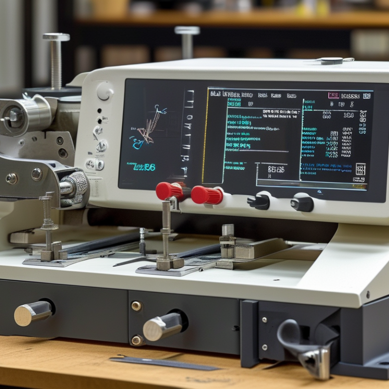
The required peel force range should come from your actual materials, not a machine catalogue. Test the adhesive, backing, liner, and substrate together. A 15 mm wide specimen allows results to be reported directly in N/15 mm. Record the expected minimum and maximum force during separation. Include unusual samples, not only clean production pieces. Some bonds fail suddenly, while others stretch and release gradually.
Choose a tester whose useful working range comfortably covers these values. If your samples normally measure 3 to 18 N/15 mm, a 0–50 N load cell may offer better control than a 0–500 N cell. Excess capacity can reduce resolution near the lower end. That detail is easy to overlook. Keep a margin for temperature changes, aging, and stronger batches. However, an oversized safety margin can also weaken measurement sensitivity.
Define the test speed, peel angle, conditioning time, and gripping method before purchase. These settings can change the measured force substantially. Confirm that the software reports average force, peak force, and force units consistently. Calibration should be traceable and documented. Ask whether the fixture keeps the strip centered and flat during testing. Small alignment errors may create uneven peeling and noisy data. A tidy range on paper may still fail in daily work. Recheck it with pilot samples before approving the machine.
Choosing a peel tester starts with the test method, not the machine display. ASTM F88 evaluates the seal strength of flexible barrier materials. ISO 8510 addresses peel adhesion between flexible and rigid adherends. These standards are related, but they are not interchangeable. Confirm the required method, specimen width, peel speed, and conditioning before comparing equipment.
Fixture geometry matters. A 90° peel fixture keeps the force path close to the surface. It can suit applications where the bonded layer must be separated upward. A 180° fixture folds the flexible material back against itself. It is common when the standard requires a straight, opposing peel path. The machine should maintain the selected angle during testing. Even a small shift can change the measured force.
Look for a stable load cell, adjustable travel, controlled speed, and clear force-versus-distance data. The grips should hold thin film without cutting or slipping. Ask how calibration is verified, and inspect the software’s reporting options.
In practical testing, alignment often causes more trouble than the motor. I have seen clean specimens produce inconsistent curves because one tail was slightly twisted. That detail is easy to miss. It is also worth testing several fixture sizes with real samples, since a technically compliant setup may still feel awkward in daily use. Temperature and humidity control may also affect results, so record them with every test series.
How to Choose a Peel Tester Machine in 2026
Choose a Load Cell, 300 mm/min Speed, and Suitable Travel Length
A peel tester starts with the load cell. Select a capacity slightly above the expected peak force, not ten times higher. Excess capacity can reduce measurement resolution. For light adhesive films, a 10 N or 20 N cell may capture small force changes more clearly. For laminates, a 100 N cell is often more practical. ASTM D3330/D3330M specifies a 300 mm/min test speed for many pressure-sensitive tape peel tests. Matching this speed improves comparison with published laboratory results.
Travel length needs careful calculation. Include the bonded section, peel angle, machine movement, and extra grip clearance. A 300 mm travel may suit short tape specimens. Longer packaging laminates may need 500 mm or more. ISO 8510-2 also emphasizes controlled separation conditions for flexible bonded materials. The machine should record force continuously, rather than displaying only a peak value. That detail matters when the curve contains unstable peeling or sudden delamination.
Tips: Confirm the load-cell range with real samples. Test three specimens, not one. Check calibration before formal testing. A higher speed is not automatically better. I have seen operators choose a large cell for “safety,” then lose useful low-force detail. That choice can weaken the report, even when the machine appears robust. Standards guide the setup, but your material may still need a small pilot study.
| Application | Typical Peak Peel Force | Suggested Load Cell Capacity | Test Speed | Suggested Travel Length | Recommended Machine Configuration | Selection Reason |
|---|---|---|---|---|---|---|
| Low-force polymer film seals | 1–5 N | 10 N or 20 N | 300 mm/min | 100–150 mm | Low-capacity load cell with fine force resolution and a smooth crosshead drive | Keeps the measured force within a useful portion of the sensor range and reduces loss of resolution. |
| Flexible packaging seals | 5–25 N | 50 N | 300 mm/min | 150–200 mm | 50 N load cell, adjustable specimen grips, and a straight, stable peel path | Suitable for routine seal-strength and peel-force testing of many flexible package structures. |
| Laminated film and foil structures | 20–75 N | 100 N | 300 mm/min | 200–300 mm | 100 N load cell with rigid grips and sufficient clearance for wider specimens | Provides additional capacity for stronger laminates while retaining practical measurement sensitivity. |
| Peelable lidding and medical-package seals | 30–150 N | 200 N | 300 mm/min | 300 mm | 200 N load cell, controlled clamping, and a travel limit of at least 300 mm | Allows a complete, stable peel segment without stopping the crosshead too early. |
| High-strength adhesive tape | 100–400 N | 500 N | 300 mm/min | 300–500 mm | 500 N load cell, reinforced grips, and a longer travel range when continuous peeling is required | Provides adequate overload margin for high-force materials and longer test strips. |
| General-purpose laboratory screening | 5–100 N | 100 N | 300 mm/min | 200–300 mm | Interchangeable load cells, adjustable speed control, and replaceable specimen grips | Offers flexibility for materials with different force levels without unnecessarily oversizing the sensor. |
| Selection Dimension | Recommended Requirement | Practical Check | Why It Matters |
|---|---|---|---|
| Load cell capacity | Select a capacity above the highest expected peel force, while keeping normal readings well below the sensor limit. | For a 25 N expected peak, a 50 N load cell is generally more appropriate than a 500 N load cell. | A correctly sized sensor improves force resolution and helps avoid overload during testing. |
| Test speed | Use 300 mm/min when the applicable packaging or seal-strength procedure specifies this speed. | Verify that the machine maintains 300 mm/min under the selected load and throughout the test stroke. | Peel force can change with speed, so the specified speed must be repeatable for comparable results. |
| Travel length | Choose at least the required peel distance plus enough clearance for specimen mounting and crosshead movement. | Use 100–150 mm for short screening tests and 300 mm or more for longer continuous peel measurements. | Insufficient travel can interrupt the peel before a representative force profile is obtained. |
| Grip adjustment | Use grips that can accommodate the specimen width and maintain alignment along the peel axis. | Check jaw opening, specimen thickness, clamping pressure, and the distance between the grips. | Misalignment or slipping can create force spikes and reduce repeatability. |
| Force measurement range | Prefer a load cell and display system that provide suitable resolution at the lower end of the expected force range. | Review the stated accuracy, resolution, tare function, and overload protection. | Low-force seals may be difficult to distinguish when a load cell is substantially oversized. |
| Data acquisition | Use a system capable of recording force and travel continuously during the peel cycle. | Confirm that the software can calculate average force, peak force, minimum force, and force-versus-distance curves. | Continuous data helps identify unstable peeling, seal defects, and abnormal force peaks. |
How to Choose a Peel Tester Machine in 2026
Calibration accuracy should be your first checkpoint. A peel curve is only useful when its force readings are traceable. ISO/IEC 17025:2017 emphasizes documented calibration competence and measurement uncertainty. Ask for the latest calibration certificate, force-range results, and uncertainty values. Do not accept “high accuracy” as evidence. For low-force samples, a large load cell may hide small differences. That mistake is common.
Sampling rate also affects the result. ASTM D3330/D3330M specifies a 180-degree peel method and commonly uses 300 mm/min. Your tester should capture enough points during fast force changes. A higher sampling rate helps reveal short peaks, adhesive transfer, and unstable backing behavior. However, more data cannot repair poor fixture alignment. Check whether the software records raw data, test speed, gauge length, and filter settings. I would compare identical samples before trusting impressive graphs.
Tips: Test at least five specimens per condition, matching ASTM D3330 practice. Record the mean, standard deviation, and coefficient of variation. Repeatability matters more than one attractive result. ISO 5725-2 explains how repeatability depends on consistent operators, equipment, and conditions. Run a short repeatability study with the same operator, then repeat it another day. If results shift noticeably, investigate temperature, peel angle, clamping pressure, or sample preparation. The weakest detail may be your real error source.
How to Choose a Peel Tester Machine in 2026
When selecting a peel tester, examine the software as carefully as the mechanical frame. A clear interface should set force, speed, angle, and travel distance without confusing menus. It should record raw data, operator details, sample identification, and calibration status. Exportable files are essential for audits and customer reports. Check whether the software supports access controls and automatic backups. In a working laboratory, poor data organization creates more trouble than slow testing. Small delays matter.
Safety features deserve practical testing, not just brochure review. Look for guarded moving parts, an emergency stop, overload protection, and a controlled return function. The machine should prevent unexpected movement after a power interruption. Ask whether operators can change force limits without authorization. Training also matters, especially when thin films break suddenly. I have found that a simple safety layout is often more useful than a crowded control panel.
Maintenance affects the true cost per test. Include calibration, fixture replacement, cleaning time, software updates, technician labor, and expected downtime. A low purchase price can become expensive if alignment checks are frequent or spare parts are difficult to obtain. Estimate total cost by dividing annual ownership expenses by usable tests, not installed capacity. For example, missed tests during calibration should count as a real cost. That estimate may be imperfect. Review it after three months of actual use.